
Hey maker! In this blog post, we will be making our own Sim Racing Pedals for our sim racing setup. For an immersive and entertaining setup, pedals are the most crucial part of sim racing setup. In our previous post, we have built a 900 Degrees DIY Steering Wheel and now it it time for the pedals. Although, there are commercial models out there from brands like Heusinkveld, Invicta, Moza, Logitech; building you own pedal system is a great experience and can save you money. The sim racing pedal setup will consist of the gas pedal, the brake pedal and the clutch pedal. After the build, you will be able to use the pedals in your favorite driving games like Dirt Rally, Asetto Corsa, Euro Truck Simulator 2 and more! Lets get into building our own Sim Racing Pedals!
Here is the video, you can watch now!
Materials and Tools for Making DIY Sim Racing Pedals
You can get materials for this project from my product lists on Amazon: DIY Sim Racing Pedals materials.
- 40×40 Square T-Profile 6mm Mounting Rod Profile
- 3 pcs 300 mm – https://bit.ly/3oo9QLy
- 2 pcs 400 mm – https://bit.ly/3qxoi5Q
- 6 pcs L Shape Inner Joints: https://bit.ly/2VGu3QJ
- 4 pcs Profile Covers: https://bit.ly/39QQiLV
- 18 pcs M5 T Sliding Nuts: https://bit.ly/3lLe66d
- 1 pcs Arduino Pro Micro
- 3 pcs 10K Potantiometer: https://bit.ly/3kpT5x6
- Throttle Spring OD: 28mm L:80mm
- Brake Spring OD:28 mm L:80 (Harder than Throttle)
- Clutch Sprint OD:28 mm L:80 (Harder than Throttle)
- Cables: https://bit.ly/3qxpGW5
- Allen Keys: https://bit.ly/33QE0iP
- 23×38 cm 5mm Thickness Wood
- 23×38 cm Floor Covering Carpet
- 18 pcs M5x16 mm Hex Cap Head Screw
- 6 pcs M5x20 mm Hex Cap Head Screw
- 6 pcs M4x40 mm Hex Cap Head Screw
- 3 pcs M5x40 mm Hex Cap Head Screw
- 3 pcs M5x35 mm Hex Cap Head Screw
- 6 pcs M3x16 mm Hex Cap Head Screw
- 12 pcs M5 Selflocking Nuts – https://bit.ly/2VGEunc
- 6 pcs M4 Selflocking Nuts – https://bit.ly/2VGEunc
- 6 pcs M3 Selflocking Nuts – https://bit.ly/2VGEunc
Tools
- Ender 3 V2 3D Printer: https://bit.ly/3mPeEcG
- 3D Filament: https://bit.ly/33NPp32
- Cutting Mat: https://bit.ly/39JQdcY
- Minleaf ML-BD2 710W Bench Drill: https://bit.ly/3lLR2UP
- Soldering Iron: https://bit.ly/36OIubE
- Solder: https://bit.ly/33QSyyS
Software
The software part of this project rather easy, thanks to the program called MMJoy. MMJoy is a software designed for hobbyists and sim racing enthusiast. It lets our pedals interface with the driving games without much configuration and effort. Thus, you don’t need much coding and software knowledge to build this project.
Let’s start by downloading MMJoy and extracting the .zip file to our computer from the link below.
https://github.com/MMjoy/mmjoy_en
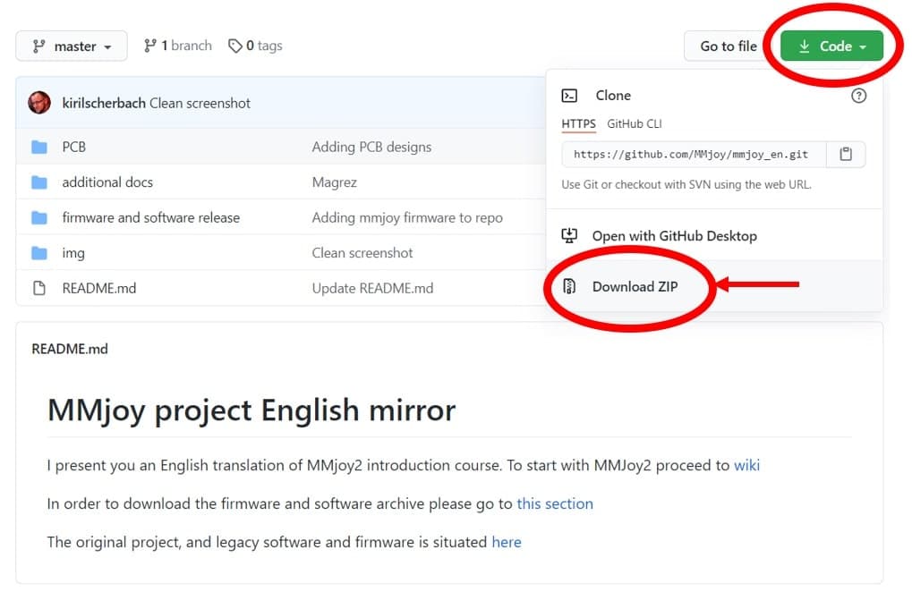
The necessary software is inside the “firmware and software release” file. Extract the “MMJoy2” file to your computer. This file includes all the necessary files like firmwares, images, softwares.
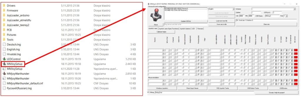
To proceed with the setup, launch the MMJoySetup application which is inside the “MMJoy2” file.
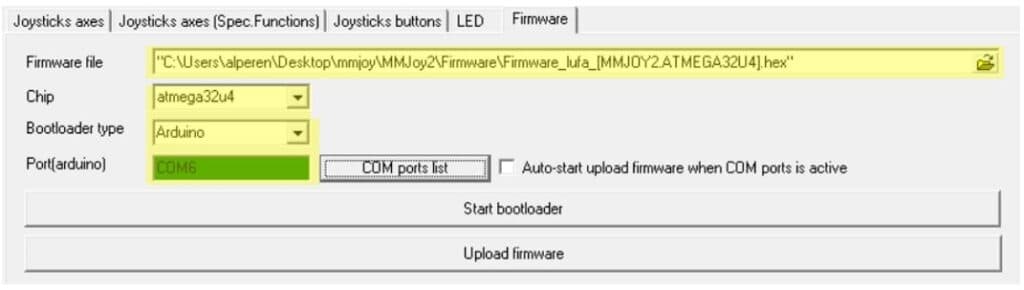
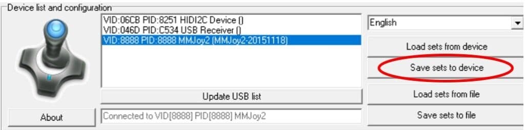
The first step is uploading the firmware to our Arduino Pro Micro card. We will do the configuration from the section indicated by the red rectangle.
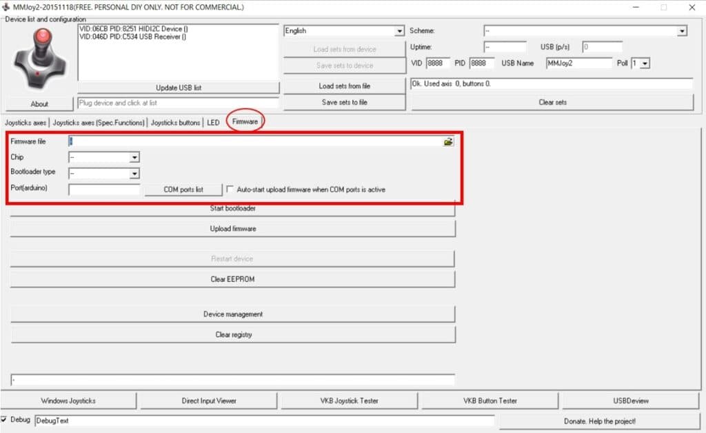
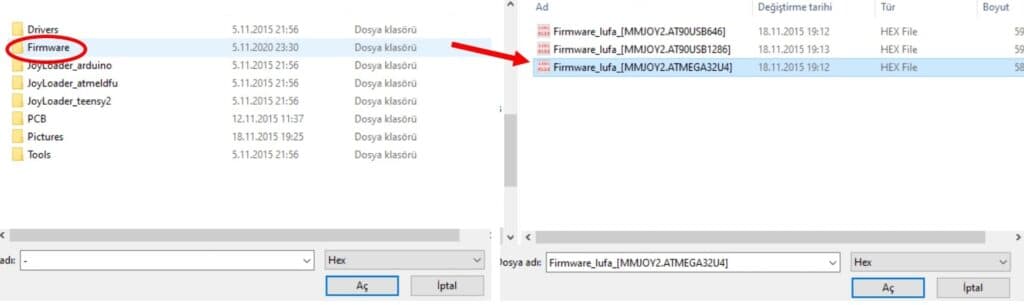
In the “Firmware file” part, we are going to choose the firmware we will upload. The file we need to choose is inside the “MMJoy2/Firmware” file. There are 3 .hex files. We need to choose the one with the “ATMEGA32U4”, since we are using Arduino Pro Micro.
After choosing the firmware file, we need to choose “atmega32u4” for the “Chip, “Arduino” for the “Bootloader Type”.
In the port selection part, you will encounter different ports after you click “COM ports list” button, but we are not going to choose one yet. Here is why:
In order to upload firmware to our Arduino Pro Micro, we need to force it to ”bootloader” mode. When the board is in bootloader mode, the port changes. Thus, we need to determine the port the board is connected to, when it is bootloader mode.
In the MMJoy2 software, click on “Device Management and choose “Ports” on the opened window. Next, press the button on the Arduino Pro Micro board twice to force the board to “bootloader” mode. Then, device manager will reload and we will be able to the port of our Arduino Pro Micro board under the “Ports” section.
Now that we know which COM port our board is connected to, we can type it to the “Port” field in the MMJoy2 software. For instance, if you see COM6 on device manager, type COM6 in the “Ports” field.
Now it is time to upload the bootloader to our board. Again, double click the button on Arduino Pro Micro and press “Upload Firmware” button on MMJoy2. Keep in mind that Arduino Pro Micro stays in bootloader mode for 8 seconds and you should do the upload in that time gap.
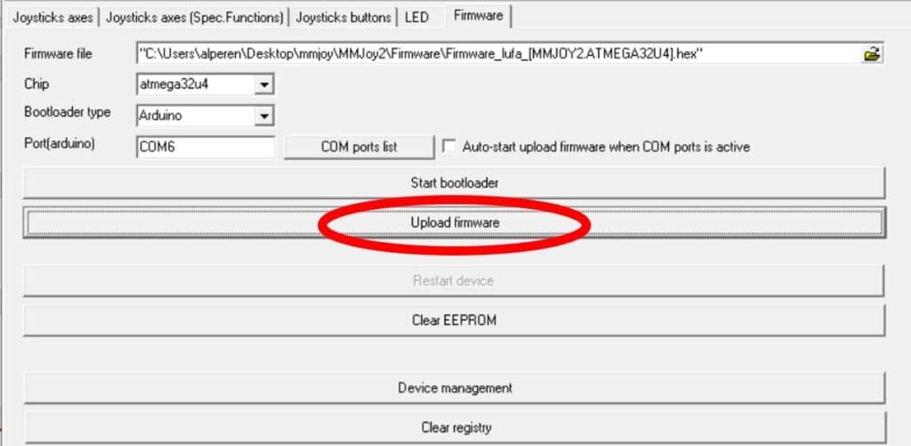
If you see an upload screen like the one below, it means that the upload is successfully done. It is time to do the necessary configurations for the potentiometers.

MMJoy lets us play with many hardware components and configure them as we like. In our project we will use 3 potentiometer, one for each pedal.
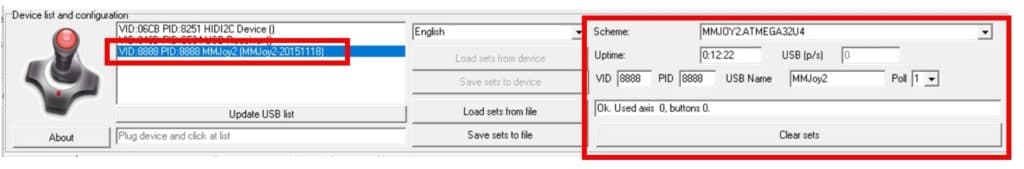
After you upload the firmware, you’ll see that the device list on the top left will change and from now on our computer will see the Arduino Pro Micro board as a joystick. We need to choose it from the device list.
Then, we need to visit the “Joystick Axes” section and do some settings on the areas indicated in the image below.
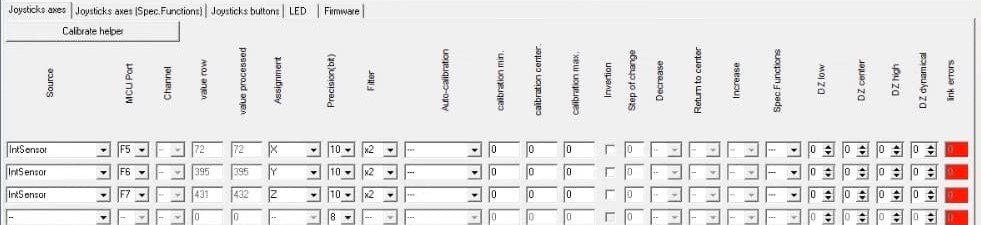
Our potantiometers are connected to the A0, A1 and A2 pin on our Arduino Pro Micro and these pins are connected to the PF7, PF6, PF5 of the MCU, respectively. Therefore, we pick F7, F6 and F5 for the “MCU port”. For the “Source”, we pick “IntSensor” and for the “Assignment” we pick “X”. We pick 10 as the “Precision” setting because Arduino Pro Micro has a 10-bit Analog Digital Converter (ADC). Finally, we press “Save sets to device” to upload the settings to our board.
After all these configurations, our hardware is ready to be used as DIY Sim Racing Pedals.
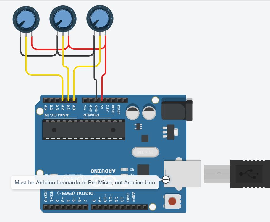
Schematics
The electronic system of this project is not very complicated. We are using 3 potentiometers, one for each pedal, in order to determine the position of the pedal. The readings from the potentiometers get communicated to the computer by the Arduino Pro Micro. The schematic for the circuit is presented below. You can use it to do the wiring on your DIY Sim Racing Pedals.
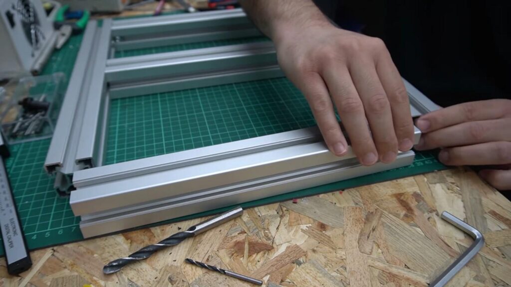
Making the Mechanic Parts
Now that the electrical and software side of the project is ready, it is time to complete the mechanical build and complete our DIY Sim Racing Pedals.
3D Files
In order to build this project, we need several 3D printed parts. To download them, you can visit this GitHub repo which has the necessary 3D parts. You can either print them on your own machines or use online services to have them printed for you.
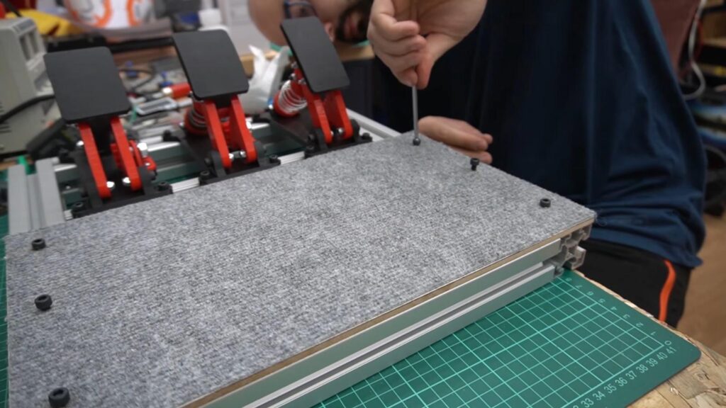
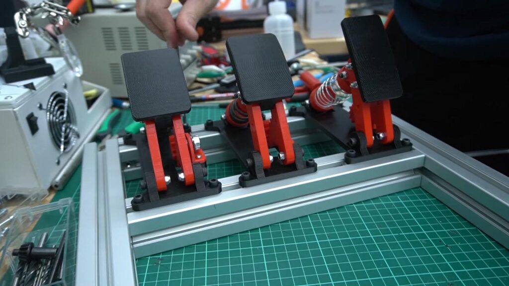
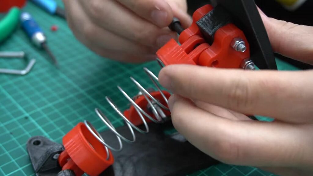
Assemble
There are various images below which will guide you in the assembly. If you want to see more visuals, you can visit the DIY Sim Racing Pedals video which includes the whole build process.


900 Degrees DIY Steering Wheel for Sim Racing
In this blog post, we have covered how to build your own DIY Sim Racing Pedals from scratch. In order to have an immersive sim racing experience while testing your pedals, we recommend you to build your own steering wheel as well. In our 900 Degrees DIY Steering Wheel for Sim Racing blog post, you can find detailed instructions on how to build your own DIY Steering wheel for your Sim Racing setup!
FAQ
MMJoy is a piece of software spesifically designed for creation or modification of game controllers. It lets you build your own game controllers that can communicate with your PC without worrying about coding and complicated configurations. It is commonly used by sim racing hobbyist and enthusiast since it makes building simulation hardware easier.
Arduino Pro Micro has Atmega32u4 chip while Arduino Uno uses Atmega328. This creates an important difference between these boards since Atmega32u4 based boards can communicate with computers natively just like a keyboard/mouse. Thanks to this functionality, Arduino Pro Micro is a common choice for projects like sim racing systems. However, you can use other boards which feature the same chip (Atmega32u4) like Arduino Leonardo.